- Published on
Considerations for sensor failure modes
- Authors

- Name
- Kassym Dorsel
Introduction
The other day I received a report of a prolonged downtime on night shift for what turned out to be a pneumatic gripper prox malfunction. The normal solution for this type of problem is simple and quick and only requires replacing the sensor. This quick solution has one major assumption; that it is known where this problematic sensor is located.
In a good PLC program sensor errors will be reported to the operator on the HMI in a concise and interpretable way to easily locate the source of the problem. This specific machine did give this information on a sensor failure, however, the PLC program did not account for all possible sensor failure modes. Due to this specific failure mode of the sensor the machine stopped mid cycle without displaying any errors or reasons for being stuck in a limbo state.
Basic Failure Modes
This will be a specific example based on prox sensors used to know the closed / opened state of a pneumatic gripper. The gripper will have two prox sensors; one for the open position and one for the closed position. There are two basic failure modes.
- Sensor always on
- Sensor always off
When using a gripper which is defined by two sensors there is a derived failure mode based on the first failure above.
- Both sensors on
Specifically for a pneumatic gripper these failure modes can be categorized into three groups.
- Physical / electrical failure of prox sensor
- Mechanical failure of gripper or of surroundings
- Setup error with regards to prox location
If the PLC program follows good OO methodology there would be a FB used for all gripper instances. Based on the aforementioned failure modes and basic usage, this FB should implement the following functionality.
- Delayed state output after prox turns on
- Error state if both prox sensors are on
- Error state if a prox is expected to turn on but it doesn't after a timeout
These two error states will catch and report the two failure modes of the sensor regardless of the root cause of the failure.
Code Example
The code below represents the main areas of FB_Pneumatic. Portions of the code have been omitted for a more succinct representation of the problem at hand.
The first two lines of the body are the delayed timers once the prox have turned on. This is ensure the next sequence step is not prematurely getting triggered since prox sensors have a fairly large activation area. A prox normally turns on before the pneumatic device has actually reached its end of stroke position and has stopped moving and it is common practice to have a 50-100ms delay to ensure correct final positions.
The next two conditional blocks create warnings on the HMI if the sensor is considered to be slower than usual at being activated. This FB records the time of every activation of the sensor and saves it in a database to be used for preemptive monitoring of the device. If for whatever reason the sensor activation time starts to slow down a warning will be given to the operator and it can be investigated before it turns into a problem.
It then checks whether both prox sensors are turned on simultaneously and emits an error. Finally the last two blocks check for a sensor timeout after a 5 second delay.
// Release and open gripper
METHOD doWait : BOOL
VAR_INPUT
END_VAR
IF ready AND waitItl THEN
	goWait := TRUE;
	goWork := FALSE;
END_IF
doWait := isWait;


// Activate and close gripper
METHOD doWork : BOOL
VAR_INPUT
END_VAR
IF ready AND workItl THEN
	goWork := TRUE;
	goWait := FALSE;
END_IF
doWork := isWork;


// Body
inWorkTm(IN := work, PT := T#50MS);
inWaitTm(IN := wait, PT := T#50MS);

IF work AND goWorkTm.IN THEN
	tt := TO_INT(goWorkTm.ET);
	IF TO_LREAL(goWorkTm.ET) > avg[2] * 1.3 AND avg[2] > 0 THEN
		msg.CreateEx(TC_EVENTS.PneumaticEventClass.WorkSlow, 0);
		msg.ipArguments.Clear().AddInt(TO_INT(goWorkTm.ET)).AddLReal(TO_INT(avg[2]));
		msg.Send(0);
	END_IF
END_IF
IF wait AND goWaitTm.IN THEN
	tt := TO_INT(goWaitTm.ET);
	IF TO_LREAL(gowaitTm.ET) > avg[1] * 1.3 AND avg[1] > 0 THEN
		msg.CreateEx(TC_EVENTS.PneumaticEventClass.WaitSlow, 0);
		msg.ipArguments.Clear().AddInt(TO_INT(goWaitTm.ET)).AddLReal(TO_INT(avg[1]));
		msg.Send(0);
	END_IF
END_IF

IF wait AND work THEN
	alarm(TC_EVENTS.PneumaticEventClass.DoubleSensor);
END_IF

goWorkTm(IN := goWork AND NOT work, PT := T#5S);
IF goWorkTm.Q THEN
	alarm(TC_EVENTS.PneumaticEventClass.WorkTimeout);
END_IF

gowaitTm(IN := goWait AND NOT wait, PT := T#5S);
IF gowaitTm.Q THEN
	alarm(TC_EVENTS.PneumaticEventClass.WaitTimeout);
END_IF
This code will cover the aforementioned failure modes and emit the necessary errors. As you must have already concluded, there is more to this story.
Uncommon Failure Mode
Going back to the machine downtime example the sensor failure mode was part of a third, much more uncommon, failure mode.
- Erratic / flickering sensor
The code is structured by using two timers, one for the delayed activation and one for the timeout error. The input to the delayed activation is the physical prox input itself and the timeout error input is the physical actuation output and the physical prox input.
A quick glance at the code and you could think it as ok. Once the prox has been on for 50ms set the in position output to on. Once the actuation is enabled and no prox input has been seen in 5s go into error. What happens once the prox starts to flicker?
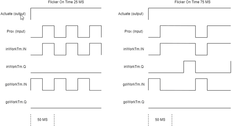
First an obvious assumption: prox delay time << prox error timeout time. In this example 50MS << 5S. Now the flickering error falls into two categories based on the frequency of the flicker.
flicker on time >= prox delay timeor specificallyflicker on time >= 50msflicker on time < prox delay timeor specificallyflicker on time < 50ms
Below is the timing diagram of both cases based on the above code. With flicker on time less and more than the output delay time. It shows the two timers and their inputs. gowork is the output to actuate the gripper and work is the prox input.
inWorkTm(IN := work, PT := T#50MS);
goWorkTm(IN := goWork AND NOT work, PT := T#5S);
Longer Flicker Time
The first case will likely work ok. This depends on the rest of the PLC program. If there's a single conditional check for the sensor to be on and then the sequence continues it will work as intended. This is because the flickering sensor stays on for long enough for the delay output timer to complete and for the program sequence to continue.
For example this program checks the prox output only once then continues and ignores it.
CASE state OF
	0:
		IF gripper.doWork() THEN
			state := 10;
		END_IF
	10:
		// Continue sequence
END_CASE
Whereas this program checks the prox output once initially, but then continuously monitors it during the next sequence of operations.
CASE state OF
	0:
		IF gripper.doWork() THEN
			state := 10;
		END_IF
	10:
		IF gripper.isWork THEN
			// do operation
			IF op_done THEN
				state := 20;
			END_IF
		ELSE
			// Gripper no longer in closed / actuated state
			// Error
		END_IF
END_CASE
The second example above will catch a flickering sensor in the program logic. However, in my opinion, this is not the correct way of doing it. Watching for this error in the parent program is tedious, error prone, and adds complexity to program. This breaks principles with scope, encapsulation and DRY (Do Not Repeat). The error discovery is not done at its root, but caught further up the stack. Program architecture and design is another topic in itself for another post.
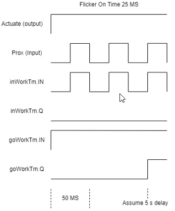
Shorter Flicker Time
What happened is the flicker on time was less than the delayed output time; flicker on < 50MS. This created an endless loop of starting both timers and resetting them before they were able to complete. Thus putting the machine into a limbo waiting state.
Solution
There is a trivial solution to make the code react to one case of the flickering issue. The two timers are independent from each other and only rely on physical signals. When you consider how the FB works its output is not the direct physical signals, byt a delayed output based on the physical signal. Therefore the error detection of the FB should also be based on this delayed output. This would now make the error timer dependent on the delayed output timer.
This would solve the case when flicker on time < prox delay time.
inWorkTm(IN := work, PT := T#50MS);
goWorkTm(IN := goWork AND NOT inWorkTm.Q, PT := T#5S);
The second case where inWorkTm.Q does turn on or flicker on time >= prox delay time requires more work. This also becomes a program design question. Do we want to catch such a flickering prox? Does it matter if the prox flickers slightly when the pneumatic device is in the correct location?
To solve this, we need another type of timer that is not found in the standard library. The basic TON timer starts its timer when the IN goes high, and resets its timer to 0 when the IN goes low. This is what gives us the current behavior. A pauseable timer gives the functionality needed - with one potential caveat. Start the timer when the actuation output goes high and pause it once the delayed output goes high.
inWorkTm(IN := work, PT := T#50MS);
goWorkTm(IN := goWork, PAUSE := NOT inWorkTm.Q, PT := T#5S);
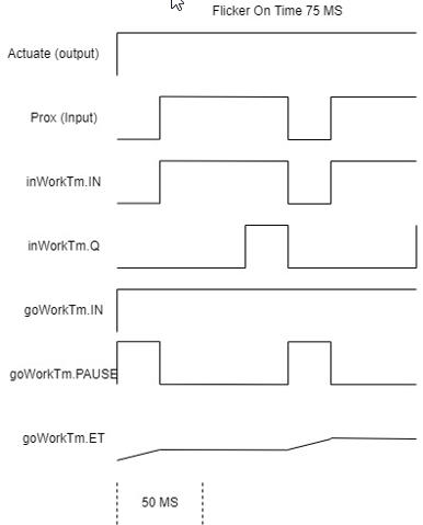
When the PAUSE input goes high the timer increases and will eventually reach the timeout time and generate the error. This is were the caveat comes into play. If the machine sequence is fast enough in that specific state or the flicker off time is much smaller than the flicker on time (small duty cycle) this will not detect the flicker error as the error timeout never gets reached. This can be tuned by changing the error time of 5s to a value that better matches the type of machine you are working on and its cycle speed.
For completeness here's an example of a TON_Pauseable.
FUNCTION_BLOCK TON_Pauseable
VAR_INPUT
    IN : BOOL;
    PT : TIME;
    PAUSE : BOOL;
END_VAR
VAR_OUTPUT
    Q : BOOL;
    ET : TIME;
END_VAR
VAR
    trig : R_TRIG;
    pausedTime : TIME;
    tm : TON;
END_VAR

IF NOT IN THEN
    pausedTime := T#0s;
END_IF

trig(CLK := IN AND PAUSE);
IF trig.Q THEN
    pausedTime := pausedTime + tm.ET;
END_IF

IF IN AND pausedTime >= PT THEN
	Q := TRUE;
	ET := PT;
ELSE
	tm(IN := IN AND NOT PAUSE, PT := PT - pausedTime);
	Q := tm.Q;
	ET := pausedTime + ton.ET;
END_IF
If any flicker in the sensor needed to be detected after its delayed output is turned on, this can also be trivially achieved with a conditional check done before the timer call.
IF inWorkTm.Q and not work THEN
	// Error
END_IF

inWorkTm(IN := work, PT := T#50MS);
goWorkTm(IN := goWork AND NOT inWorkTm.Q, PT := T#5S);
This is a very tight control as if the sensor is off for 1 PLC cycle then the device will error out. Is this tight of a error checking needed? Depends on how critical that specific sensor is in your application. I would be more inclined to turn this into a warning for a potential sensor failure instead of a machine stopping error. The warning message would need to be debounced otherwise it can be sent hundreds of times.
IF inWorkTm.Q and not work THEN
	IF workFlickerWarn THEN
		// Send warning
		workFlickerWarn := FALSE;
	END_IF
END_IF

inWorkTm(IN := work, PT := T#50MS);
goWorkTm(IN := goWork, PAUSE := inWorkTm.Q, PT := T#5S);

IF NOT goWork THEN
	workFlickerWarn := FALSE;
END_IF
In this last example you can also see I use the pauseable timer. This is probably the best of both worlds.
Conclusion
This shows there can be many subtleties even when it comes to such a basic automation item as a prox sensor or gripper. A simple program can be easily created in a relatively short time, however does it really cover all potential failures? Perhaps a better question, and this is a basic engineering decision of tradeoff. Is it even worth the time, effort, CPU computation power, etc to look for this type of error?
To give you the bigger picture, this machine has been running for over 5 years with close to a hundred pneumatic actuators all using this same code. There have been many times where prox sensors failed in the two basic failure modes for whatever reason and the machine correctly alarmed. There has been just 1 occurrence of this flicker failure up to now and none since.
In my mind, the pauseable timer is the best solution and will be implemented to prevent this type of prolonged downtime, regardless of how unlikely it is. What will you do with your sensors?